Command-line utility
QEDA command line utility is installed by using NPM:
sudo npm install -g qeda
Run in order to list all available commands:
qeda --help
| Command | Description | Example |
|---|---|---|
| Add component definition to configuration file (with preloading from remote repository if necessary) | qeda add ti/iso721 |
|
| completion | Display completion script | source <(qeda completion) |
| Set/get configuration parameter (see Parameters list) | qeda config output kicad |
|
| Generate libraries for EDA according to configuration file | qeda generate mylib |
|
| Add ground symbol to configuration file | qeda ground GND_DC |
|
Load component description from remote repository and caching to library subdirectory (without adding to configuration file) |
qeda load ti/iso721 |
|
| Add power supply symbol to configuration file | qeda power +5V_DC |
|
| reset | Delete current configuration file (use with attention!) | qeda reset |
| sort | Sort components and nets in configuration file alphabetically | qeda sort |
| Generate test library with one component only (does not affect current configuration file but can load some parameters from it) | qeda test ti/iso721 |
All configuration parameters and list of added components are saved in .qeda.yaml configuration file which is created by the utility. It is a good idea to add this file to your source version control system.
add
Firstly this command looks for COMPONENT's YAML-description in library directory (relatively to current working directory). In case of its absence utility tries to download correspondent description from remote repository. Successful downloading leads to caching this description file in library directory and add corresponding record to .qeda.yaml configuration file. When called for the second time, utility will use cached file instead of loading it from Internet.
If there is no appropriate description file in local library directory nor in remote library, utility will return an error.
Some components may be presented in several variations. In order to add only one variation to library you need to point this variation after @ character:
qeda add ti/sn74lvc1g07@sot-23
See also: load
completion
Generate completion script for shell and output it to stdout. Depending on Linux distribution one may save this script to system directory:
qeda completion | sudo tee /usr/local/etc/bash_completion.d/qeda
# or
qeda completion | sudo tee /etc/bash_completion.d/qeda
config
This command allow to tune individual configuration parameters of future library of electronic components (see Parameters list). To set PARAM you need to provide VALUE as second argument to command. To check the parameter set one should omit the VALUE argument.
generate
The final command which generates a library of electronic components according to settings found in .qeda.yaml configuration file.
ground
Add global ground symbol. There are three optional prefixes for ground net name:
signalchassisearth
qeda ground GND
qeda ground signal/GNDS
qeda ground chassis/GNDC
qeda ground earth/GNDE

See also: power
load
This command loads and caches component description from remote repository regardless of its existence in library directory without adding to configuration file.
See also: add
power
Add global power symbol.
See also: ground
reset
This command completely deletes .qeda.yaml configuration file. It is good idea to use it after some experiments before creating release library.
Use this command with caution because it can erase all your work.
sort
This command sorts components and nets in .qeda.yaml configuration file in alphabetical order. This may be useful if you wish to edit this file manually in future. But sorting after starting schematic design may cause some direct annotation issues due to land pattern naming sequence.
It is strongly recommended to use this command only before starting schematic design.
test
This command will produce a library with the only COMPONENT. The purpose of this command is to check look and integrity of electronic component. Library will be named test_<conponent>.
This command does not use components list from .qeda.yaml configuration file nor affects it in any manner. But other parameters set by config command are taken into account during library generation.
Parameters list
General parameters:
| Parameter | Type | Default | Description |
|---|---|---|---|
connection.timeout |
integer (ms) | 5000 | Maximum connection timeout for component description loading from remote repository |
output |
string | 'kicad' | Output library format. The supported outputs are: 'kicad', 'geda', 'coraleda' |
Schematic symbol related parameters:
| Parameter | Type | Default | Description |
|---|---|---|---|
symbol.gridSize |
float (mm) | 2.5 | Grid cell size. |
symbol.fill |
string | 'foreground' | Symbol contour filling type. Options: foreground, background, none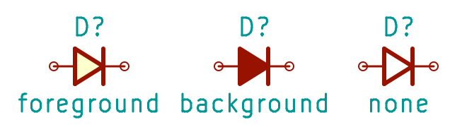 |
symbol.fontSize.default |
float (mm) | 2.5 | Default font size |
symbol.fontSize.name |
float (mm) | 2.5 | Font size for component name |
symbol.fontSize.pin |
float (mm) | 2.5 | Font size for pin name |
symbol.fontSize.refDes |
float (mm) | 2.5 | Font size for reference designator |
symbol.lineWidth.default |
float (mm) | 0 | Default line width |
symbol.lineWidth.thick |
float (mm) | 0.6 | Thick line width |
symbol.lineWidth.thin |
float (mm) | 0.2 | Thin line width |
symbol.shortPinNames |
boolean | false | Do not use alternative pin names separated by / char |
symbol.space.attribute |
float (mm) | 2 | Space between symbol contour and attribute |
symbol.space.default |
float (mm) | 2 | Default space |
symbol.space.pin |
float (mm) | 1.5 | Space between symbol contour and pin number |
symbol.style |
string | 'default' | Symbol style. Options: 'default', 'GOST' |
Land pattern related parameters:
| Parameter | Type | Default | Description |
|---|---|---|---|
pattern.ball.collapsible |
boolean | true | Collapsing option for BGA packages (according to IPC-7351) |
pattern.clearance.leadToHole |
float (mm) | 0.1 | Gap between through-hole lead and hole |
pattern.clearance.padToMask |
float (mm) | 0.05 | Gap between pad's metal and mask edges |
pattern.clearance.padToPad |
float (mm) | 0.2 | Gap between neighboring pads |
pattern.clearance.padToSilk |
float (mm) | 0.2 | Gap between pad's metal and silkscreen drawing |
pattern.decimals |
integer | 3 | Number of digits after decimal point (precision) in generated files |
pattern.densityLevel |
string | 'N' | Component placement density level (according to IPC-7351). Options: 'L', 'N', 'M' |
pattern.fontSize.default |
float (mm) | 1 | Default font size |
pattern.fontSize.refDes |
float (mm) | 1.2 | Font size for reference designator |
pattern.fontSize.value |
float (mm) | 1 | Font size for value |
pattern.lineWidth.assembly |
float (mm) | 0.1 | Line width for drawing in assembly layer |
pattern.lineWidth.courtyard |
float (mm) | 0.05 | Line width for drawing in courtyard layer |
pattern.lineWidth.default |
float (mm) | 0.2 | Default line width |
pattern.lineWidth.silkscreen |
float (mm) | 0.12 | Line width for drawing in silkscreen layer |
pattern.maximum.cornerRadius |
float (mm) | 0.2 | Maximum pad corner radius. Applied only when pattern.smoothPadCorners is set to true |
pattern.minimum.drillDiameter |
float (mm) | 0.2 | Minimum drill diameter (according to PCB manufacturer capabilities) |
pattern.minimum.maskWidth |
float (mm) | 0.2 | Minimum mask strip width (according to PCB manufacturer capabilities). Has higher priority over pattern.clearance.padToMask |
pattern.minimum.ringWidth |
float (mm) | 0.2 | Minimum ring width for vias and through-hole pads (according to PCB manufacturer capabilities) |
pattern.minimum.spaceForIron |
float (mm) | 0 | Minimum space between lead and its pad edges |
pattern.preferManufacturer |
boolean | true | Prefer component manufacturer's dimensions rather than IPC-7351 standard while land pattern calculating |
pattern.polarityMark |
string | 'dot' | Shape of polarity mark (near to the first pad). Options: 'dot' |
pattern.ratio.cornerToWidth |
float | 0.25 | Pad's corner radius to its width ratio. Applied only when pattern.smoothPadCorners is set to true |
pattern.ratio.padToHole |
float | 1.5 | Proportion for pad size calculation from hole diameter |
pattern.smoothPadCorners |
boolean | false | Replace rectangle pads by rounded rectangles. Parameters are set by pattern.ratio.cornerToWidth and pattern.maximum.cornerRadius.Warning: Supported by nightly development build of KiCad only |
pattern.style |
string | 'default' | Pattern style. Options: 'default' |
pattern.tolerance.default |
float (mm) | 0.1 | Default size tolerance |
pattern.tolerance.fabrication |
float (mm) | 0.1 | Fabrication tolerance (provided by component manufacturer) |
pattern.tolerance.placement |
float (mm) | 0.1 | Placement tolerance (provided by component placement equipment) |